The resent cantaloupe scare has left produce shelves in grocery stores empty. Listeria-tainted cantaloupes have caused a major crisis in the United States. Listeria monocytogenes is a type of bacteria found only in soil and water. It is killed by pasteurization and cooking, but can grow in refrigerated temperatures. Listeriosis can also lead to lethal or disabling encephalitis and meningitis. This bacteria, linked to cantaloupe, has a death toll of as many as ten people and at least 60 people have been reported ill. According to the FDA’s latest report, “Colorado-based Jenson Farms Inc. shipped Listeria-tainted cantaloupes to five more states than originally thought, bringing the total number of states affected by the outbreak to twenty-two.” Although only certain states have cantaloupe that have been affected, many consumers are being advised to stop consuming all cantaloupe. This halt of consuming cantaloupe has caused a sharp drop in demand for cantaloupe and has also eliminated the supply of the melon. The Listeria outbreak has dramatically decreased the sales and production of cantaloupe, which has negatively affected profits for all cantaloupe growers, even those growers that were producing safe melons in a non-tainted region. The consumer is now most likely to purchase other types of produce which will cause a rise in demand for these other fruits.
Thursday, October 13, 2011
Monday, May 2, 2011
Apple Launcher
Our engineering group was assigned the task of using materials found in the shop, and anything that we could find at home, to construct the best apple launcher, with the goal of beating all competition in the distance traveled by the apple's trajectory. Where to begin?
Design Process
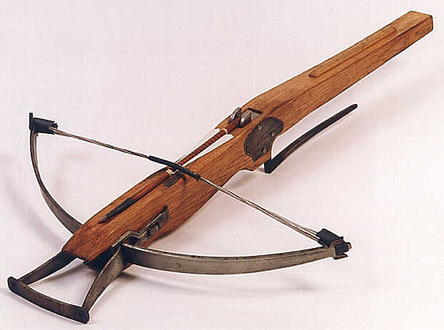
Our group, consisting of Nick, Michael, Jack and Eric, spent a considerable time generating ideas to find the best design meeting the requirements. Our only limitation was that the catapult must be able to fit inside of a 60x60x60 cm box. While other groups modeled their designs based on what had been historically successful, our group, being intellectually adventurous, thought about a novel approach. While at a Dallas Mavs game, we marveled at the enormous power that the T-shirt elastic catapults appeared to produce. With this in mind, our group thought about applying a design model similar to a cross-bow.
 Our group shared and cogently collaborated our ideas and then drew plans for proposed models.
Our group created a series of drawings to apply our slingshot approach into a functional catapult. Once we had a basic design created we divided up the tasks among our group members. Nick was in charge of designing a carriage to carry the apple as it accelerated out of the device. Nick started by taking a piece of large PVC pipe and cutting it in half with the Rikon band saw. Then he took a small piece of plastic sheet and used the band saw and the bell sander to give it a circular shape to match diameter of the PVC. He then used the epoxy to attach the two plastic pieces. The two plastic pieces were later braced together by a metal clasp that Jack diligently tightened because the epoxy could not hold the the pieces together as they soon separated. This problem only temporarily was solved because during our test lauch it broke. Our group had to tighten the clasp and add plastic braces to hold the two plastic pieces together. Another problem our group faced with the carriage was that the carriage sepparated from the wooden piece that the metal rod ran through. This piece of wooden 2x4 was used to attach the carriage to the elastics. To solve this, our group entered 3 screws through the plastic sheet backing into the 2x4. During our final assembly of our many pieces, we realized that the carriage was being suspended from a single rod, which spun freely. Since the carriage wanted to face down, our group had to add another plane of support by bending a coat hanger aroung the front end of the carriage. Originally, this coat hanger was attached only by some electrical tape. After our first test launch, we soon realized that the coat hanger is mangled as it crashes at high speed to the end of the rail. In order to allow our catapult work for more than one time, our group tightened the coat hanger to the carriage permanently with a few tight screws, preventing the coat hanger from sliding and not working for the next launch.
While Nick was creating and perfecting the carriage, Michael, Jack and Eric created the railings for the pin to slide through. Michael took the initiative of finding the correct dimensions and lengths of the 1X4's. Jack and Eric cut the pieces to size using the compound miter saw and marking the correct angles and measurements with some basic geometry and a T-square. Eric then took the two rails and cut a slot about an inch wide and spanning the majority of the length of the rail, before realizing that there was an inefficiency. Eric saw that the friction between the metal rod and the rough wood would slow down the carriage, and then he decided to line the rails with cut PVC. Jack, Nick and Michael cut the PVC using the Band Saw and then Eric glued it to the rails with epoxy and further securing it with some electrical tape.
While Nick and Eric were absent, Michael and Jack were busy asssembling the rails to the 60x60 cm base that they cut from plywood. By using plastic braces, the rails and vertical supports were attached. Then Michael and Jack screwed the rails to the plywood and braced them with 2x4's using screws which went through the bottom on the ply-wood. During this time, our group realized that the glue holding the carriage together was not sufficient. Because of its inability we placed screws into the plastic to make sure our carriage was secure. Our carriage also did not want to face in the correct direction when placed into position, therefore we bent a coat hanger to provide support. The time came to power our catpult with the sergical tubes and bungee cords. Because the elastics only pull the carriage for a partial distance of the rail, we tried to maximize this distance by tieing the elastics closer to the base. We attached a cross piece between the rails and tied both ends to this wooden piece which we attached with screws. The elastic was then wrapped over the metal rod we intserted in the top of the rail and finally attached to the metal rod behind the carriage. We had to be careful to not tie the surgical tubes too tight as they would crush the coat hanger while it is in resting position. To solve this problem, we inserted wooden restraints for transportation and time between launches.
Calculations and Factors We Considered


Units and More Calculations
As labeled in our sketches above, we converted all measurement into SI units to better understand and put our design into perspective.
Conversions/Dimensions/Calculations:
1. The catapult was required to fit inside of a 60cm x 60cm x 60cm box
2. As accepted in projectile motion physics, the ideal launching angle to maximize distance (assuming perfect external elements are omitted) is 45 degrees. Therefore, we angled our catapult to fire at 45 degrees.
3. Our rails which guided the apple inside of the carriage were made from 1x4's. This can be translated into 2.5 cm x 10.2 cm. On their longer base (directed upward) the trapezoidal prisms were 84.85 cm. On their shorter base, these rails were 64.6 cm (84.85 cm - 8 in (8 in is 20.3 cm) = 64.6 cm) (see drawing for basic 45, 45, 90 degree triangle calculations and proof)


 http://www.ajdesigner.com/phpprojectilemotion/range_equation.php
Projectile Motion In Basic Form
When the angle of a projectile is 45 degrees, the range is maximized because the time of horizontal motion allowed is greatest as a result of a balance in energy put into the x and y vectors. As explained above, gravity acts equally on all objects in the y direction by constantly accelerating them downward at 9.8 m/s^2 whether they are moving or not.
Assembly Process
We diligently assembled our catapult, conquering challenges as they arose. Our design went through a metamorphosis as we kept trying to make the catapult more efficient and conserve energy by eliminating friction and impediments. This may have been a reason for our catapult's short launch distance- our catapult was very complicated and had many moving parts which had to operate in order to get a good launch.


One modification, or addition, to our original design that we made was inserting PVC pipe lining into the pin channel, as friction between the metal pin and plastic was far less than the rough wood cuts. Our original idea of mounting the elastics was also modified. We thought that if we increased the length of the bungees, there would be less drag. At certain point, the bungees were no longer accelerating the apple in the carriage, but were actually colliding with the apple's path and slowing it down. To accommodate this original design flaw, we tied the bungees down toward the base and had them wrap on top of the pins that acted as a pivotal point or hinge for the elastics. After developing our model, our group carefully considered how to make an effective carriage to carry the apple. We cut a PVC pipe in half and glued/screwed a circular backing to it. The plastic carriage was then backed by a cut from a 2X4 in which we drilled a hole in order to insert a metal rod. Once we had the catapult assembled, we soon realized that there was not a brace to prevent the carriage from falling face-down and dropping the load. As a result of Michael and Eric's creativity, we were able to save the carriage that had received great attention by manipulating a pliable coat hanger under the front of the carriage to keep it aimed in the correct, forward, upright direction. The solution of the coat hanger was not perfect and was only temporary because launching the device resulted in its destruction.


Borrowed Pictures
http://tedlington.files.wordpress.com/2009/12/crossbow.jpg
http://www.ajdesigner.com/phpprojectilemotion/range_equation.php
Design Process
Our group, consisting of Nick, Michael, Jack and Eric, spent a considerable time generating ideas to find the best design meeting the requirements. Our only limitation was that the catapult must be able to fit inside of a 60x60x60 cm box. While other groups modeled their designs based on what had been historically successful, our group, being intellectually adventurous, thought about a novel approach. While at a Dallas Mavs game, we marveled at the enormous power that the T-shirt elastic catapults appeared to produce. With this in mind, our group thought about applying a design model similar to a cross-bow.

Our group created a series of drawings to apply our slingshot approach into a functional catapult. Once we had a basic design created we divided up the tasks among our group members. Nick was in charge of designing a carriage to carry the apple as it accelerated out of the device. Nick started by taking a piece of large PVC pipe and cutting it in half with the Rikon band saw. Then he took a small piece of plastic sheet and used the band saw and the bell sander to give it a circular shape to match diameter of the PVC. He then used the epoxy to attach the two plastic pieces. The two plastic pieces were later braced together by a metal clasp that Jack diligently tightened because the epoxy could not hold the the pieces together as they soon separated. This problem only temporarily was solved because during our test lauch it broke. Our group had to tighten the clasp and add plastic braces to hold the two plastic pieces together. Another problem our group faced with the carriage was that the carriage sepparated from the wooden piece that the metal rod ran through. This piece of wooden 2x4 was used to attach the carriage to the elastics. To solve this, our group entered 3 screws through the plastic sheet backing into the 2x4. During our final assembly of our many pieces, we realized that the carriage was being suspended from a single rod, which spun freely. Since the carriage wanted to face down, our group had to add another plane of support by bending a coat hanger aroung the front end of the carriage. Originally, this coat hanger was attached only by some electrical tape. After our first test launch, we soon realized that the coat hanger is mangled as it crashes at high speed to the end of the rail. In order to allow our catapult work for more than one time, our group tightened the coat hanger to the carriage permanently with a few tight screws, preventing the coat hanger from sliding and not working for the next launch.
While Nick was creating and perfecting the carriage, Michael, Jack and Eric created the railings for the pin to slide through. Michael took the initiative of finding the correct dimensions and lengths of the 1X4's. Jack and Eric cut the pieces to size using the compound miter saw and marking the correct angles and measurements with some basic geometry and a T-square. Eric then took the two rails and cut a slot about an inch wide and spanning the majority of the length of the rail, before realizing that there was an inefficiency. Eric saw that the friction between the metal rod and the rough wood would slow down the carriage, and then he decided to line the rails with cut PVC. Jack, Nick and Michael cut the PVC using the Band Saw and then Eric glued it to the rails with epoxy and further securing it with some electrical tape.
While Nick and Eric were absent, Michael and Jack were busy asssembling the rails to the 60x60 cm base that they cut from plywood. By using plastic braces, the rails and vertical supports were attached. Then Michael and Jack screwed the rails to the plywood and braced them with 2x4's using screws which went through the bottom on the ply-wood. During this time, our group realized that the glue holding the carriage together was not sufficient. Because of its inability we placed screws into the plastic to make sure our carriage was secure. Our carriage also did not want to face in the correct direction when placed into position, therefore we bent a coat hanger to provide support. The time came to power our catpult with the sergical tubes and bungee cords. Because the elastics only pull the carriage for a partial distance of the rail, we tried to maximize this distance by tieing the elastics closer to the base. We attached a cross piece between the rails and tied both ends to this wooden piece which we attached with screws. The elastic was then wrapped over the metal rod we intserted in the top of the rail and finally attached to the metal rod behind the carriage. We had to be careful to not tie the surgical tubes too tight as they would crush the coat hanger while it is in resting position. To solve this problem, we inserted wooden restraints for transportation and time between launches.
Calculations and Factors We Considered

Proof of a "45-45-90" right triangle side length correlation- this was used to find the maximum length of the rails. In this case, x=60cm and c=84.85cm (60 times root 2)

"45-45-90" right triangle applied to create optimal dimensions

The Design of Our 2 Pin Channel Pieces

This is how we envisioned that our launcher would operate
Units and More Calculations
As labeled in our sketches above, we converted all measurement into SI units to better understand and put our design into perspective.
Conversions/Dimensions/Calculations:
1. The catapult was required to fit inside of a 60cm x 60cm x 60cm box
2. As accepted in projectile motion physics, the ideal launching angle to maximize distance (assuming perfect external elements are omitted) is 45 degrees. Therefore, we angled our catapult to fire at 45 degrees.
3. Our rails which guided the apple inside of the carriage were made from 1x4's. This can be translated into 2.5 cm x 10.2 cm. On their longer base (directed upward) the trapezoidal prisms were 84.85 cm. On their shorter base, these rails were 64.6 cm (84.85 cm - 8 in (8 in is 20.3 cm) = 64.6 cm) (see drawing for basic 45, 45, 90 degree triangle calculations and proof)


Projectile Motion In Basic Form
Assembly Process
We diligently assembled our catapult, conquering challenges as they arose. Our design went through a metamorphosis as we kept trying to make the catapult more efficient and conserve energy by eliminating friction and impediments. This may have been a reason for our catapult's short launch distance- our catapult was very complicated and had many moving parts which had to operate in order to get a good launch.
WORK IN PROGRESS

FINAL PRODUCT

One modification, or addition, to our original design that we made was inserting PVC pipe lining into the pin channel, as friction between the metal pin and plastic was far less than the rough wood cuts. Our original idea of mounting the elastics was also modified. We thought that if we increased the length of the bungees, there would be less drag. At certain point, the bungees were no longer accelerating the apple in the carriage, but were actually colliding with the apple's path and slowing it down. To accommodate this original design flaw, we tied the bungees down toward the base and had them wrap on top of the pins that acted as a pivotal point or hinge for the elastics. After developing our model, our group carefully considered how to make an effective carriage to carry the apple. We cut a PVC pipe in half and glued/screwed a circular backing to it. The plastic carriage was then backed by a cut from a 2X4 in which we drilled a hole in order to insert a metal rod. Once we had the catapult assembled, we soon realized that there was not a brace to prevent the carriage from falling face-down and dropping the load. As a result of Michael and Eric's creativity, we were able to save the carriage that had received great attention by manipulating a pliable coat hanger under the front of the carriage to keep it aimed in the correct, forward, upright direction. The solution of the coat hanger was not perfect and was only temporary because launching the device resulted in its destruction.


Performance
Our catapult was a disappointment. Our group saw a great potential in this design but the tensional force of the bungees was enormous and proved to be uncontrollable. The device was so powerful that when it was launched, it self-destructed and was easily damaged as a result of its complexity and fragile nature. This was evident in the fact that the first launch was significantly better than the next two. The catapult had several parts that were glued together and fell apart in the high stress joints. Back-up bracing would have been beneficial and made this design more successful.
In Conclusion...
As awesome and original as our catapult design was, it did not win the contest. In many ways it was a disappointment. Our group worked hard to create a quality machine, but too many complex factors and moving parts allowed room for error. Our apple soared 11 yards. In future catapults, our group would try develop a simpler more elegant machine that takes advantage or torque and more efficiently directs the elastic power.
Borrowed Pictures
http://tedlington.files.wordpress.com/2009/12/crossbow.jpg
http://www.ajdesigner.com/phpprojectilemotion/range_equation.php
Monday, March 28, 2011
Final Bridge


This is the video of the final test of our bridge! The bridge wiped out all competition, holding a whopping 128 pounds!
This engineered bridge solved many of the problems of our old bridges, focusing on lateral and vertical braces in the form of triangles, the strongest shape. The tri-ply "skeleton" of this bridge was found to be the strongest per-pound way to connect the popsicle sticks, with the outer layers splitting the difference in length of the inner chain of sticks, and therefore minimizing the vulnerability of the joints of the bridge. Overall, our group was very proud and excited by this sturdy bridge. Future modifications would include exploring with using string in an effective way, something which we found nearly impossible throughout the process. Our group even braided a string which was used in our second prototype, but we did not see this as an advantage to the strength of the bridge. This bridge weighed 201 grams, was 53 cm in length, 10 cm wide, and 9 cm tall. The next version we would make would have more vertically oriented sticks on the lower level, toward the outer lengths of the bridge, the location of the break. This bridge was very solid, and any significant improvements would require exploration with other "skeleton" shapes and forms.

Note that this design, unlike previous models, has a top layer that has the identical width to the base. This change was made to provide stronger contacts between braces, which held the bases together, and the levels of the bridge. Also note the increased lateral bracing on this bridge, compared to previous models.

This is the progression of our bridges... The oldest bridge is in the foreground, and the final bridge is in the background.
Calculations
Data
1 popsicle stick = 1.1 g
1 popsicle stick + one popsicle stick volume of hot glue = 4.5 g
Inertia of Popsicle stick in multi-dimensions
Which way is stonger?

The Popsicle Stick Horizontal-
The Popsicle Stick Vertical-
The Vertical Popsicle Stick has much greater Inertia, therefore much greater force is needed to strain or break the stick.
mass suspended from the bridge : bridge's mass ratio
After our final test, we found one calculation which we found to be incredibly impressive. Our bridge weighed in just over 200 grams (201 to be exact). Our bridge successfully held 128 lbs before the weights crashed to the floor as seen in our video. Using the conversion factor from pounds to grams, (1 pound = 453.59 grams), we found out how many grams our bridge held (58,059.82 g). By dividing the suspended weight by the weight of the bridge, we found that our bridge was able to support x300 its weight!
1:300
1 popsicle stick = 1.1 g
1 popsicle stick + one popsicle stick volume of hot glue = 4.5 g
Using the data above we concluded that the same volume of hot glue as one popsicle stick weighed much more than the popsicle stick (3.4 g is found using subtraction to represent the glue's mass vs. the 1.1 g of a popsicle stick)
Which way is stonger?
The Popsicle Stick Horizontal-
The Popsicle Stick Vertical-
The Vertical Popsicle Stick has much greater Inertia, therefore much greater force is needed to strain or break the stick.
mass suspended from the bridge : bridge's mass ratio
After our final test, we found one calculation which we found to be incredibly impressive. Our bridge weighed in just over 200 grams (201 to be exact). Our bridge successfully held 128 lbs before the weights crashed to the floor as seen in our video. Using the conversion factor from pounds to grams, (1 pound = 453.59 grams), we found out how many grams our bridge held (58,059.82 g). By dividing the suspended weight by the weight of the bridge, we found that our bridge was able to support x300 its weight!
1:300
Prototype 2
After testing both Ant Bridge and Prototype 1, our group realized that Prototype 1 would be a better design, making it our final design. The bridge was 217 g, 54 cm long, 10 cm tall, and 14 cm wide. The main difference between prototype 1 and 2 was that we made many more triangles on the second prototype. We made the base and the top of our bridge mainly out of triangles. This new strategy was better than our last prototype's strategy, but yet it was not perfect because the top of our bridge was not flat, and unproportional to the bottom. This caused the top of our bridge to start to snap when compression increased. Our future modifications were to make the top of our bridge equal in width to the bottom, as well as orient the top-layer of popsicle sticks vertically to increase inertia, giving our bridge more strength. Also, the joints of prototype 1 proved very weak, as the popsicle sticks met at an angle. In the future, glued areas that experience great stress when weight is applied should have a larger surface of contact, and ideally flush. Another point of weakness for this bridge was that the upper railings had cross-supports in an "X" style. The bracing technique used created stress on the bridge, even when weight was not being applied, therefore causing the top level to twist. In future models, the top layer's popsicle sticks will be oriented vertically and bracing will not apply stress to the skeleton.

Prototype 2- Notice a progression in the efficiency of the mass of this bridge, compared to the previous designs.


Prototype 2- Notice a progression in the efficiency of the mass of this bridge, compared to the previous designs.


Thursday, March 24, 2011
Ant Bridge
Our group decided that we needed to come up with two small, but different designs and put them to the test to find out which worked best. Eric and Jack took one approach, while Michael and Nick took another. Nick took pride in his design which was later named Ant Bridge due to its minuscule size. Ant Bridge was designed by using a base of posicle sticks guled together with five single popsicle sticks coming to a center point above, and then pieces of string were added to the bottom of the bridge to help with tension. Ant Bridge weighed 54 grams. It was 20 centimeters in lenthgh, 12 centimeters in width, and 9 centimeters tall. Ant Bridge failed at 75 pounds. The length of Ant Bridge also contributed to its high holding capacity. Ant bridge was a very short bridge, therefore the force (tau) was smaller due to the very short radius for the force to be applied. Another reason Ant Bridge was successful, was that our group learned that the fewer joint parts with a greater surface area of contact, the stronger the bridge would be. We did not consider Ant Bridge to be a failure, but the primary problem with it was that it was too small. It was necessary to use a large amount of glue for this model. Future modifications of our design will consist of a much larger bridge and less glue, so that we can really understand if this design can be successful at a large scale, under the weight requirements.


Wednesday, March 9, 2011
Prototype 1
When we were assigned this project, our group was spilt in half into 2 teams, working on two very different bridge designs. One was abstract with a novel design, and the other was a variation on a conventional, modern bridge. Eric and Jack started on the later concept and it was named Prototype 1. Our first prototype was 33.5 cm long, 11 cm wide, 12 cm high, and weighed 114 g. Our prototype was based on a trapezoidal prism figure. It held 65 pounds before it broke. The center of the lower side rail broke first, which then caused the bridge to snap, twist and collapse. We decided that our faliure was due to a weakness in our base. Our base consisted of 3 popsicle sticks vertically oriented, with minimal bracing in the horizontal or vertical axes. Our modifications consisted of using more triangles to cross brace the base, making it stronger on the bottom in future models. Overall, it was a good first prototype, giving us much to learn from and modify in future bridges.


Subscribe to:
Posts (Atom)